TMP102 temperature sensor
Requirements
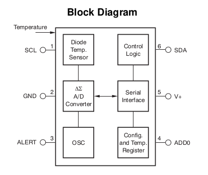
The TMP102 is a 6 pin chip capable of measuring the temperature. It has three modes of communication: SMBus, Two-Wire and I2C. This manual will use the I2C interface.
Pins
- SCL: Serial clock, used for I2C. Connected to the μC SCL
- SDA: Serial data, used for I2C. Connected to the μC SCL
- ALERT: over temperature alert output
- ADD0: address select, connect to GND or V+
Registers
The temperature is stored in a either 12 bit or 13 bit read only register, depending on whether Extended Mode was activated. Byte 1 is the MSB, Byte 2 is the LSB. 1 bit equals 0.0625°, while negative numbers are stored as twos complement. The bit D0 of byte 2 indicates Normal (0) or Extended Mode (1).
Example: a register value of 0011 0010 0000 indicates a temperature of 50°
since 0b0011 0010 0000 = 800 and 800 * 0.0625 = 50.
If the MSB is 1, the temperature is negative. A register value of
1110 0111 0000 indicates a temperature of -25°, because the twos complement
of 0b1110 0111 0000 is 0b0001 1001 0000 (formed by inverting all bits and
adding 1). This is the absolute value of the temperature. Convert to decimal
and add a negative sign. This gives -400 (dec), which can be multiplied by the
above resolution to get -25.
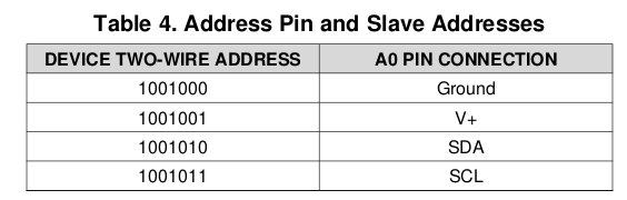
Bus address (ADD0)
Depending on how the ADD0 pin is connected, the bus address of the sensor
changes:
Reading and writing
To access a register, the master must write the register address to the pointer register, which is indicated by the first byte transferred after the address byte, while keeping the R/W bit low to indicate a write.
To read the register at the address in the pointer register, a START condition, the slave address and the R/W bit high starts a read operation. This can also be used to issue repeated read commands.
Device modes
Conversion mode (CR0 and CR1)
Default. Temperature is measured continually, then converted and stored in the temperature register. The bits CR0 and CR1 configure the conversion rate.
Shutdown mode (SD)
SD bit set to 1 enables the shutdown mode.
One shot (OS)
When the device is in shutdown mode, writing a 1 to the OS starts a single temperature conversion.
Common actions
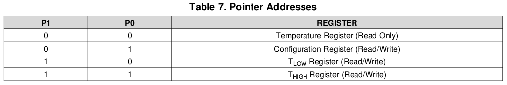
The pointer register uses the two LSB to decide which of the data registers must respond to the command.
Temperature reading
To read the temperature, one needs to perform the following steps:
- Write the register address of the temp register to the pointer register. This
means sending a command which contains
- an address frame made of
- the devices 7 bit address
- the bit 1 to indicate a writing command
- a data frame made of
- 6 0-bits
- the register bits
0b00as defined in Table 7
- an address frame made of
- Receive the two temperature bytes off the SDA line, which consist of
- the MSB containing bits 11:4
- the LSB containing bits 3:0 and 4 padding 0 bits.
Shutting down
To shut the device down, one needs to first read the configuration register and then write an update value using the following steps:
- Write the register address of the config register to the pointer register:
- an address frame made of the devices 7 bit address and the bit 1 to indicate a reading command
- a data frame made of 6 0-bits and the bits
0b01as defined in Table 7
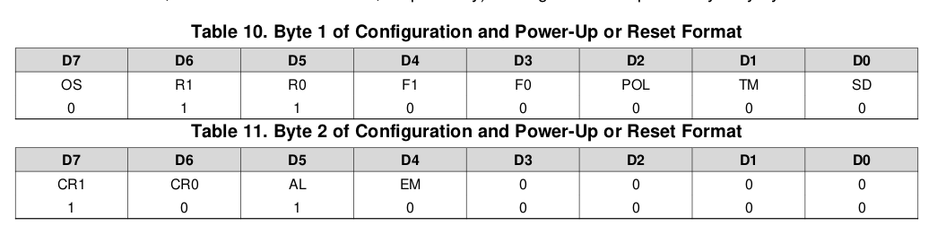
- Receive the two configuration bytes of the SDA line as defined in Table 10
- Write the register address of the config register to the pointer register:
- an address frame made of the devices 7 bit address and the bit 1 to indicate a writing command
- a data frame made of 6 0-bits and the bits
0b01as defined in Table 7 - a data frame (as MSB) set to
0x00000001 - a data frame (as LSB) set to
0x00000000